Introduction
I wanted to monitor my electricity usage. The house has an electronic meter with a flashing LED so the task becomes one of detecting the flashes from the LED and counting them. The selection of sensor is explained in Sensors to detect LED output on electricity meters.
Meter to Arduino
The electricity meter and the consumer unit is housed in a cupboard. It wasn’t feasible to place the Arduino in the cupboard for two reasons. Firstly there are no sockets in the cupboard to provide power and it wasn’t feasible to add one. Secondly, I intended to add an Ethernet shield to the Arduino to allow it to communicate the energy readings via the home network and therefore it makes more sense to place the Arduino near the home router.
Telephone wire is used to connect the light sensor to the Arduino. Three conductors are needed for +5v, ground and signal. A note was made of the colour of the selected conductors before the insulation on conductors were stripped back by about 10mm. The bare conductor was twisted round the leg of the light sensor to make a mechanical joint and then soldered. Finally each joint was wrapped in red, black and blue insulating tape as appropriate. Then black tape was wrapped round all three joints and continued down a further 50mm (2 inches) to provide strain relief.
The TSL251 is simply placed over the LED and held in place with duct tape. This also blocks any ambient light, improving reliable sensing of the LED flashes.
The telephone cable was then neatly run from the cupboard to the Arduino location.
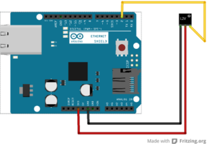
Breadboard connectors were then cut in half, stripped and soldered to the ends of the conductors, as noted above, in the telephone cable. Red, black and yellow connectors were selected for +5v, ground and signal and connected to the Arduino as in the diagram above.
References
TSL251 Datasheet – tsl25x-light-to-voltage-sensor-301932.pdf