Introduction
Following on from the last three blogs I thought it worthwhile checking the quality of the signal from the light sensors. Using an oscilloscope I measured the pulse at the Arduino pins.
Results
What surprised me was the quality of the pulse was good. I thought I would need a decoupling capacitor close to the light sensor to compensate for the relatively long signal line to the Arduino.
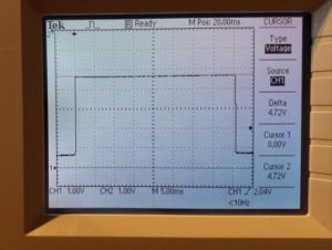
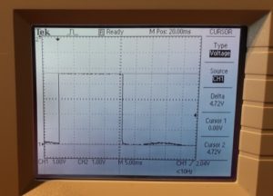
Apart from the different pulse widths the performance is very similar. The rising and falling edges are clean and there’s little sign of ringing. The different pulse width are due, of course, to the difference makes of the two meters.
While the oscilloscope was connected I carried out a few tests.
- Effect of ambient light. Removing the tape shielding the light sensor added a DC offset of about 1v.
- Effect of room lighting. Switching on the room lights added another 0.8v
The total DC offset could be up to 1.8v. This is getting close to the switching threshold of the Arduino input. This implies some form of shielding of the meter LED and the light sensor over it are essential.